


 互动量:435
主要内容
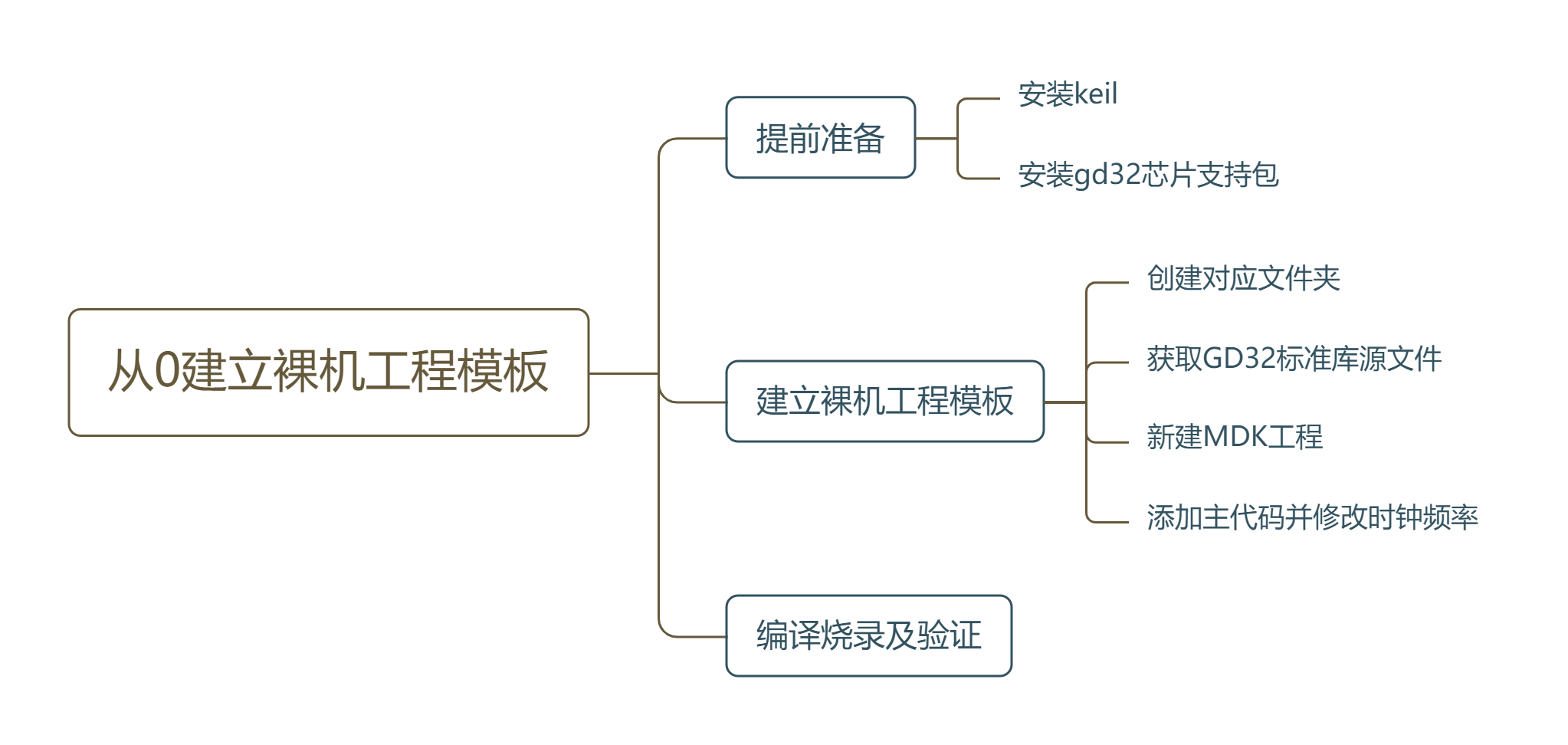
提前准备
参考立创梁山派入门教程资料中的开发环境介绍和工程模板创建,下载并安装最新的KEIL(MDK)软件和GD32官方的器件支持包(推荐用离线安装的方式)
建立裸机工程模板
1_创建对应文件夹
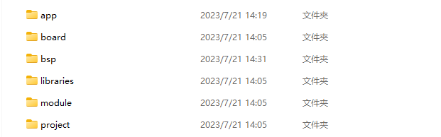
> ├─app
> ├─bsp
> ├─board
> ├─libraries
> ├─module
> └─project
>
> app:存放应用程序,由用户编写
> bsp:存放和底层相关的支持包
> board:存放板子初始化文件和链接脚本
> libraries:存放各种库文件,CMSIS,芯片固件库,文件系统库,网络库等
> module:主要存放各种软件模块,比如软件定时器,PID,FIFO,状态机等
> project:存放工程文件(目前只支持MDK5)
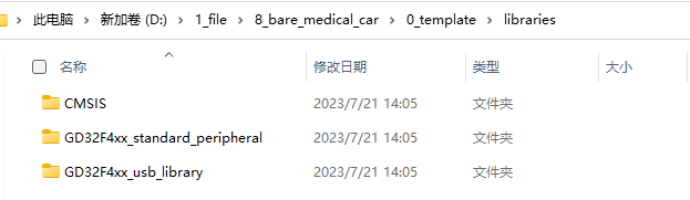
2_获取GD32标准库源文件
打开链接,下载最新的GD32F4xx Firmware Library,我这里下载的是V3.0.4,发布时间为2023-03-07。
将其解压后的Firmware文件夹里面的内容放入上面建立的libraries文件夹里面:
3_新建MDK工程
在上面建立的project文件夹里面创建一个MDK(V5)文件夹用来存放keil MDK ARM V5版本的工程文件。 打开Keil uVision5创建一个新的工程: 单击->Project->New uVision Project ->选好芯片型号=GD32F470ZG。
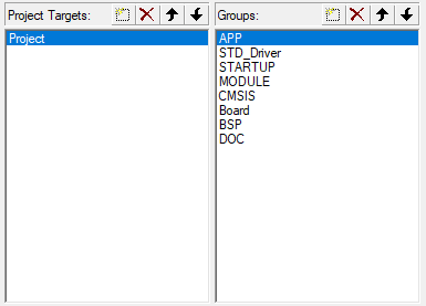
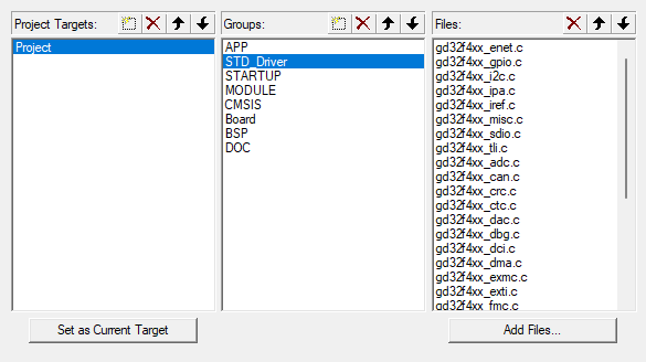
右键Target->单击Manage Project Items 如下所示设计分组(双击可以修改名字):
将\libraries\CMSIS\GD\GD32F4xx\Source\ARM目录下的startup_gd32f450_470.s添加到STARTUP组里(注意最后要点击对话框左下角的OK按钮才能生效)
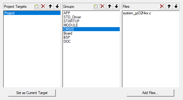
将\libraries\CMSIS\GD\GD32F4xx\Source\目录下的system_gd32f4xx.c添加到CMSIS组里面:
将\libraries\GD32F4xx_standard_peripheral\Source目录下的所有文件添加到STD_Driver组里面:
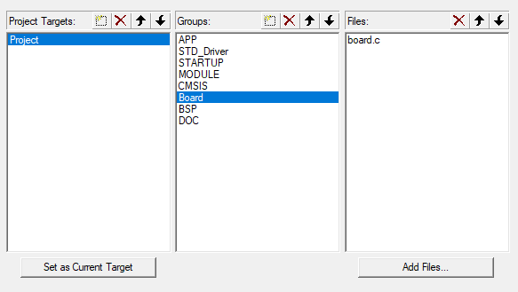
在board文件夹下新建board.c和board.h文件:
board.c:
#include
#include

static __IO uint32_t g_system_tick = 0;

/*!
    \brief      this function handles NMI exception
    \param[in]  none
    \param[out] none
    \retval     none
*/
void NMI_Handler(void)
{
}

/*!
    \brief      this function handles HardFault exception
    \param[in]  none
    \param[out] none
    \retval     none
*/
void HardFault_Handler(void)
{
    /* if Hard Fault exception occurs, go to infinite loop */
    while(1) {
    }
}

/*!
    \brief      this function handles MemManage exception
    \param[in]  none
    \param[out] none
    \retval     none
*/
void MemManage_Handler(void)
{
    /* if Memory Manage exception occurs, go to infinite loop */
    while(1) {
    }
}

/*!
    \brief      this function handles BusFault exception
    \param[in]  none
    \param[out] none
    \retval     none
*/
void BusFault_Handler(void)
{
    /* if Bus Fault exception occurs, go to infinite loop */
    while(1) {
    }
}

/*!
    \brief      this function handles UsageFault exception
    \param[in]  none
    \param[out] none
    \retval     none
*/
void UsageFault_Handler(void)
{
    /* if Usage Fault exception occurs, go to infinite loop */
    while(1) {
    }
}

/**
  * @brief  This function is executed in case of error occurrence.
  * @param  None
  * @retval None
  */
void Error_Handler(void)
{
    /* USER CODE BEGIN Error_Handler */
    /* User can add his own implementation to report the HAL error return state */
    while (1)
    {
    }
    /* USER CODE END Error_Handler */
}

/*!
    \brief      configure systick
    \param[in]  none
    \param[out] none
    \retval     none
*/
void systick_config(void)
{
    /* setup systick timer for 1000Hz interrupts */
    if(SysTick_Config(SystemCoreClock / 1000U)) {
        /* capture error */
        while(1) {
        }
    }
    /* configure the systick handler priority */
    NVIC_SetPriority(SysTick_IRQn, 0x00U);
}

/*!
    \brief      this function handles SysTick exception
    \param[in]  none
    \param[out] none
    \retval     none
*/
void SysTick_Handler(void)
{
    g_system_tick ++;
}

uint32_t get_system_tick(void)
{
    return g_system_tick;
}

/**
 * This function will initial GD32 board.
 */
void board_init(void)
{
    /* NVIC Configuration */
#define NVIC_VTOR_MASK              0x3FFFFF80
#ifdef  VECT_TAB_RAM
    /* Set the Vector Table base location at 0x10000000 */
    SCB->VTOR  = (0x10000000 & NVIC_VTOR_MASK);
#else  /* VECT_TAB_FLASH  */
    /* Set the Vector Table base location at 0x08000000 */
    SCB->VTOR  = (0x08000000 & NVIC_VTOR_MASK);
#endif

    systick_config();

}

/**
 -  @brief  用内核的 systick 实现的微妙延时
 -  @note   None
 -  @param  _us:要延时的us数
 -  @retval None
*/
void delay_us(uint32_t _us)
{
    uint32_t ticks;
    uint32_t told, tnow, tcnt = 0;

    // 计算需要的时钟数 = 延迟微秒数 * 每微秒的时钟数
    // 后面的80是补偿值,因为语句运行也需要时间。
    // 补偿值是GD32F470在240Mhz运行条件下用逻辑分析仪测出来的。
    ticks = _us * (SystemCoreClock / 1000000) - 80;

    // 获取当前的SysTick值
    told = SysTick->VAL;

    while (1)
    {
        // 重复刷新获取当前的SysTick值
        tnow = SysTick->VAL;

        if (tnow != told)
        {
            if (tnow < told)
                tcnt += told - tnow;
            else
                tcnt += SysTick->LOAD - tnow + told;

            told = tnow;

            // 如果达到了需要的时钟数,就退出循环
            if (tcnt >= ticks)
                break;
        }
    }
}
board.h
#ifndef __BOARD_H__
#define __BOARD_H__

#include "gd32f4xx.h"
#include "stdint.h"
#include "stdio.h"
#include "gd32f4xx_libopt.h"
#include "gd32f4xx_exti.h"

void board_init(void);
uint32_t get_system_tick(void);
void delay_us(uint32_t _us);

#endif
同样的,把他添加到Board分组中:
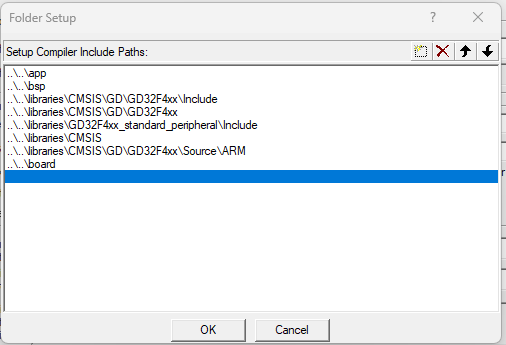
加入头文件路径:
继续补全头文件路径如下图所示:
将默认编译器改为V5:

添加宏定义USE_STDPERIPH_DRIVER,GD32F470,并勾选C99 Mode,点击OK保存设置:
4_添加主代码并修改时钟验证
立创梁山派是板载了一个25M的高精度外部晶振的,而GD32的固件库默认是用内部精度不高的高速晶振,将system_gd32f4xx.c文件中的
#define __SYSTEM_CLOCK_240M_PLL_IRC16M          (uint32_t)(240000000)
//#define __SYSTEM_CLOCK_240M_PLL_8M_HXTAL        (uint32_t)(240000000)
//#define __SYSTEM_CLOCK_240M_PLL_25M_HXTAL (uint32_t)(240000000)将上面的__SYSTEM_CLOCK_240M_PLL_IRC16M注释掉,把__SYSTEM_CLOCK_240M_PLL_25M_HXTAL解除注释,改成下面这样:
//#define __SYSTEM_CLOCK_240M_PLL_IRC16M          (uint32_t)(240000000)
//#define __SYSTEM_CLOCK_240M_PLL_8M_HXTAL        (uint32_t)(240000000)
#define __SYSTEM_CLOCK_240M_PLL_25M_HXTAL (uint32_t)(240000000)在app目录中新建如下所示的main.c文件:
#include "board.h"

#define RCU_LED2  RCU_GPIOD
#define PORT_LED2 GPIOD
#define PIN_LED2 GPIO_PIN_7

void led_gpio_config(void)
{
    rcu_periph_clock_enable(RCU_LED2);
    gpio_mode_set(PORT_LED2,GPIO_MODE_OUTPUT,GPIO_PUPD_NONE,PIN_LED2);
    gpio_output_options_set(PORT_LED2,GPIO_OTYPE_PP,GPIO_OSPEED_50MHZ,PIN_LED2);
}
/*!
    \brief      main function
    \param[in]  none
    \param[out] none
    \retval     none
*/
int main(void)
{
    board_init();
    led_gpio_config();
    while (1)
    {
        gpio_bit_write(PORT_LED2,PIN_LED2,SET);
        delay_us(1000000);
        gpio_bit_write(PORT_LED2,PIN_LED2,RESET);
        delay_us(1000000);
    }
}
将main.c文件内容替换为下面这个,全编译烧录之后,没有错误和警告,按下立创梁山派的复位按键后,LED2灯开始时闪烁就说明工程模板建立成功了。
编译烧录验证
点击Rebuild按钮编译全工程,确保下方是0 Error(s), 0 Warning(s)
选择你当前所使用的下载器(我这里用的立创梁山派自带的下载器,属于DAP下载器),连接好立创梁山派的供电和下载线,点击下载按钮,成功后按下复位键,如果立创梁山派的LED2开始间隔一秒亮一次,说明模板工程搭建OK了。
\n#学习资料# #include#
#ifndef__BOARD_H__#
#includegd32f4xx.h#
#includestdio.h#
#includeboard.h#
#definePORT_LED2GPIOD#
#学习资料#
#include#
#ifndef__BOARD_H__#
#includegd32f4xx.h#
#includestdio.h#
#includeboard.h#
#definePORT_LED2GPIOD#
#学习资料#


登录 或 注册 后才可以进行评论哦!
还没有评论,抢个沙发!